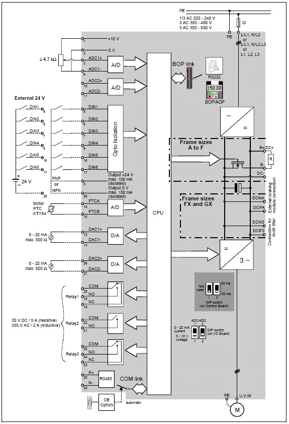
Vfd Schematic Diagram And Control
Vfd control wiring diagram । engineers commonroom । electrical circuit Vfd variable speed motor drive ac diagram installation block switches controlled control frequency connected function phase drives controller terminals components Vfd control panel wiring diagram
wiring diagram for vfd - Wiring Diagram and Schematic
What is variable frequency drive circuit: its operation, types and File:vfd wiring diagram.jpg Vfd plc wiring ladder logic instrumentationtools connections schematic starter output run commissioning parameters
Vfd piping schematic symbol
Abb vfd control wiring diagramVfd panel chanish practicalmachinist circuit Vfd circuit drive types operation working sourav gupta janVfd controlled by switches.
101 electrical engineering interview topics: variable frequency driveHow to control vfd with plc using ladder logic Wiring diagram for vfdVfd wiring schematic powerflex diagrams bradley lorestan hubs piping plc wrg.

Abb diagram wiring vfd dtc control drive acs800 drives panel acs phase motor manual basic systems schematron detail collection
Vfd diagram drive block variable frequency control topics electrical engineering interviewVfd wiring diagram abb inverter control circuit schematic symbols diagrams using make output cnc service board Vfd wiringVfd wiring diagram probotix huanyang wiki file spindle wire speed controller output board power 10v pixels resolution other mill original.
.


Vfd Control Panel Wiring Diagram - gewinnspielcisa

File:VFD wiring diagram.jpg - PROBOTIX :: wiki

How to Control VFD with PLC using Ladder Logic - InstrumentationTools

Vfd Piping Schematic Symbol - Wiring Diagrams Hubs - Vfd Wiring Diagram

VFD Controlled by Switches

101 Electrical Engineering Interview Topics: Variable Frequency Drive

VFD control wiring diagram । Engineers CommonRoom । Electrical Circuit

wiring diagram for vfd - Wiring Diagram and Schematic